


There’s an old saying that still gets tossed around fairly often:
“There’s no replacement for displacement.”
Actually, there is a replacement for displacement. It’s called “technology.” However, like most everything else in life, technology comes at a price, and it’s seldom cheap.
In the automotive world, technology has progressed by leaps and bounds over the last few decades, providing enthusiasts with seemingly limitless choices when it comes to engine components such as rotating assemblies, camshafts and valvetrain components, and perhaps most importantly, cylinder heads and induction systems. The latest and greatest state-of-the-art aftermarket cylinder heads and that monster roller cam kit are never any further than a phone call or an online shopping cart away.
There’s no denying that often these components can make a dramatic difference in power output. I’ve seen a swap to aftermarket cylinder heads knock a full second off of a car’s e.t. with no other changes. It’s hard to argue with those kind of results. These parts certainly have their place.
However, all too often I see enthusiasts getting duped into believing that they need these parts to achieve what really often amount to relatively modest performance goals, when more often than not, factory components are more than adequate to do the job. I credit this phenomenon to a combination of advertising bombardment and the “eye candy” factor. Nothing draws a crowd better than the latest aftermarket aluminum heads or the latest billet gee-gaws when the hood gets popped at the local choke & puke burger joint. And we can’t forget (no matter how hard we might try) the guy on the Saturday morning automotive high performance tv shows screaming at the top of his lungs how you simply can not live another day without the latest billet gizmos piled under your hood.
Advertising at its finest.
If this is what you’re after, you might as well stop reading right here.
Fact of the matter is, the money you might otherwise spend on all the latest trick aftermarket goodies can likely be spent much more productively elsewhere for all but the wildest street-bound rides. Why spend your hard-earned money on the latest and greatest aftermarket parts if they’re not really needed?
As such, I have absolutely no intention of trying to convince you that you need all the latest gadgets and gizmos in the front of your favorite speed shop catalog to build something that runs great on the street and at the track–quite the contrary; you don’t need every trick aftermarket component you can get your hands on under your hood to build a great running car–no matter how much the guy on tv tries to convince you otherwise.
Which brings me to the focus of this 496 build. I wanted to take advantage of some new school technology and combine it with some proven old school technology to build a strong running engine that’s still based mostly on OEM components. As I’m a firm believer in cubic inches, I decided to build a “new-old school” 454 that’s based upon the legendary LS6, but takes advantage of a little modern technology with a stroker crank, better reciprocating components, as well as a little more aggressive camshaft timing. Still, there’s nothing even remotely “trick” about this engine–actually, in comparison with current trends, this engine is decidedly UN-trick.
So why a 496 instead of a 427or 454 based engine?
As I said, I’m a believer in cubic inches (up to a practical limit). The core engine I started with had a thoroughly-worn cast crank that was already turned .030″-.030″, so it obviously wasn’t going to go back into service inside this engine. Since it didn’t cost any more to build a 496 than it would have to build a 427 or 454 based engine (including the cost of a new aftermarket mid-level crankshaft), the choice was obvious.
So what’s the goal?
First and foremost, to use as many OEM parts as possible in an attempt to keep costs within a reasonable range, and to retain as much of an OEM appearance as possible. The ultimate objective will be to build a relatively low-revving (+/- 6500 rpm) engine that will take my 4-speed `67 Chevelle project deep into the 11 second zone on premium pump gas in full street trim, all while maintaining acceptable street manners and solid reliability.
Accomplishing this goal will require spending money only where it will do the most good, which means (in no particular order); No aluminum heads. No roller cams. A simple flat tappet cam will get the job done here. Not even a set of roller rocker arms. No single plane intakes–a factory aluminum dual plane intake will suffice. No monster high-dollar carburetors. A factory 855 cfm vacuum secondary Holley will be pressed into service for initial testing. A mechanical secondary carb will be tested later.
The engine originally saw dyno time at the facilities of the legendary “Ohio George” Montgomery’s speed shop in Dayton, Ohio. Before I go any further, I’ll tell you up-front–don’t expect some bogus, over-inflated “car magazine” dyno numbers. I used George’s facility for several reasons, not the least of which is the fact that his dyno is very conservative–or in George’s own words, “stingy.” There are several other local dyno facilities that I could’ve just as easily used which would’ve likely produced much more “magazine-friendly” power figures, but what’s the point? I have no desire to publish bogus dyno numbers, and I’m not the one who’s trying to get you to buy every “trick-of-the-week” part they can to keep my advertisers happy.
My initial power goal was somewhere around 525 horsepower and similar torque figures, all in full street trim through the same mufflers that will be used on the car. To put those numbers into perspective, consider that a well-tuned 454 LS6 running through open headers should normally make around 440-460 HP and 480-ish ft.lbs of torque on a realistic dyno. I’m only looking for roughly 75 horsepower on top of that just by the added cubes, a slightly better factory carb and intake, and a little more cam timing. I don’t necessarily expect to attain those numbers right off the bat, and a second trip to the dyno is already planned after some minor revisions to the original combination. Also note that initial dyno testing was intentionally conducted in a “worst-to-best configuration” manner; as I had several modifications planned to achieve the final combination, I needed to start out with certain things that I know will not work, then progress my way to the final combination. Otherwise I would be unnecessarily repeating several assembly/dis-assembly steps. The biggest modifications from the original combination will be some minor cylinder head and intake manifold porting, and I may try a few different cams in it as well. Once that’s done the engine will go back to the dyno for follow-up pulls to see what the modifications were actually worth.
Now that that’s out of the way, follow along with the build and we’ll see what kind of noise this thing can make on the dyno when it’s all said and done. It will be a while before the car itself is track ready, but once it is, we’ll find out what this project is truly capable of.
Here is the foundation for the 496 build-up: A rather unexciting 454 2-bolt main block liberated from the remains of a rotting 1970’s Chevy truck. Why not a 4-bolt block? Because at the power level this engine will make, 4 bolt mains are simply not needed.
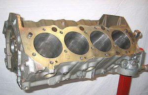
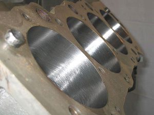
After the normal trip through the hot tank, the block was pressure checked, then sent to the boring bar where the cylinders were taken out to 4.305″. The last .005″ gets saved for the hone, which was done with torque plates.

Once the block had been bored and honed, it was square-decked to spec to leave the pistons -.010″ in the hole. Tech tip: If your machine shop uses a boring bar that registers off the deck surface, make sure they deck the block BEFORE boring it to keep the bores parallel with the crank centerline. This boring bar registers off the mains, so all is good.
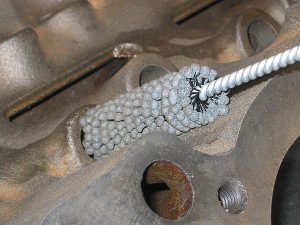
Plenty of grit and other little nasties get left embedded in the cylinder walls after honing. If this trash isn’t removed, the engine will destroy even the best set of rings in very short order.
After several thorough scrub sessions with hot soapy water and a variety of scrub brushes, the bores were ready to be cleaned. ATF (automatic transmission fluid) does a superb job of lifting the offending materials from the cylinder walls.
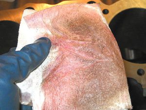
Lots’a nasties right there. Just think of what all that grit and grime would do to your nice shiny new pistons and rings.
It took about a half-dozen scrubbings per bore before the paper towels came out clean. Patience definitely is a virtue at this point of the job.
Big block Chevrolet engines are sometimes known for having an appetite for flat tappet camshafts. Several factors can contribute to the issue such as improperly located lifter bores (the OEM’s weren’t always so accurate when it came to machining tolerances), and tight lifter bore clearances. Today’s modern aggressive cams also tend to put the lobes closer to the edge of the lifters which can exacerbate the problem. As such, it’s best not to get too carried away when it comes time to choose a cam.
As a matter of standard practice, I run a flex hone through the lifter bores just to help clean up any “boogers” that might be hiding inside, and to help remove any varnish that may have been left behind after the block was cleaned.
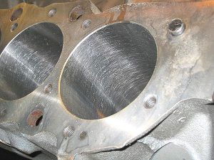
Since a stroker crank was destined for this engine, I needed to ensure there was enough clearance between the connecting rods and the bottom of the bores and the oil pan rails. While the oil pan rails cleared with room to spare, the rods were uncomfortably close to the bottom of the bores, although they did technically clear. The bores were marked where the interference potential was noted, and an hour or so spent with a carbide burr and a grinder left everything considerably more comfortable. Note that the relief was deburred to avoid damaging the piston skirts at BDC.

Tech tip: Whenever ANY non-original rods are used, it’s a wise idea to check for sufficient rotating clearances.
Next up: Component selection, degreeing the cam, checking for valve-to-piston clearance and bearing clearances.
The crankshaft used in this engine is an Eagle 4130 forged steel unit featuring a 4.25″ stroke (.250″ over a stock 454).
Clevite CB743-H rod and MS829 H main bearings were used to clear the generous journal radius found on most aftermarket crankshafts such as this one.
As a side-note: Given the quality of aftermarket crankshafts available today, I gave strong consideration to a cast crank for this build. Were it not for the fact that this engine is destined to live in front of a 4-speed transmission, I would have likely opted for a cast crankshaft.
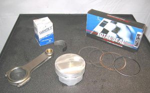
The pistons originally used were Probe forged units which featured an 18 c.c. dome, and utilize a desirable 1/16″-1/16″-3″16″ ring package over the OEM 5/64″-5/64″-3/16″ configuration. The narrower rings reduce friction which frees up power, but they’re still more than adequate to provide a long life on the street. The connecting rods are Scat 6.385″ H-beam units, which are .250″ longer than stock. These rods offer vastly superior strength to an OEM rod, and their greater length allows for a lighter, shorter piston which also reduces friction and wear.
When you consider the cost of reconditioning a set of 30+ year-old OEM rods with who-knows-how-many millions of cycles on them, the choice for an aftermarket rod becomes obvious. The benefits of an aftermarket rod far outweigh the slight cost difference compared to reconditioning OEM rods.
For piston rings, I chose a CR9190 60 Total Seal pre-gapped moly piston ring set with standard tension oil rings for this build.
Why pre-gapped when most people prefer file-fit rings? Simple. For a street engine, I’ve found that Total Seals pre-gapped rings come in right on spec where I want them out of the box. During mock-up, these rings came in spot-on with .022″-.024″ gap across the board, which is exactly where I wanted them in the first place. Were this a dedicated race engine I would have opted for file-fit rings.
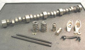
Again keeping with the “non-trick” premise of this build, an off-the-shelf Crane solid lifter cam was chosen. The cam specs out at .592″/.612″ lift (net) and 256/264 degrees duration at .050″, and is ground with a 108 degree lobe separation angle. I degreed it in per the cam card at a 105 degree intake centerline. Having used it in several previous builds, I chose this cam because I’ve found it to be extremely versatile, and for a somewhat “old tech” cam, this one works very well. While some might think this cam a bit lumpy for the street, first-hand experience has shown me that 500 cubic inches calms it right down.
A few notes regarding camshaft choices for street engines;
One of the most common mistakes I see people make is choosing a camshaft that’s inappropriately spec’ed for their engines, erring most often on the too-large side. It’s easy to get carried away in the search for maximum power, but an engine will almost always run better with a cam that’s slightly too small in comparison to one that’s slightly too big.
When choosing a cam from your favorite cam manufacturer’s catalog, keep in mind that the advertised rpm ranges are usually based on median engine displacement figures. Engine displacement has a dramatic effect on how a camshaft will behave. A camshaft that’s considered wild in a 283″ engine would be considerably milder in a 400″ engine. If you’re not sure which way to go, ask your cam manufacturer for their recommendations, or consult with a trusted engine builder for their advice. If you’re still not certain which way to go, remember it’s almost always better to err on the smaller side, especially in regards to duration numbers.
Roller cams:
I only advocate running solid roller camshafts on the street under very specific circumstances. More often they’re simply not needed to achieve most reasonable performance goals, and the lifespan of a solid roller cam and lifters on the street can be questionable. Most have heard the stories about a friend of a friend who has a big solid roller that’s been living on the street for 50K+ miles without a problem, and while that’s entirely possible, it’s certainly the exception rather than the norm. It’s not so much a question of if a solid roller will fail, but more inevitably when it will fail. When one does, the results are often catastrophic. (Been there, done that, got the busted roller lifters to show for it–not to mention the big, ugly dent it put in my bank account). There are some alternatives to help ensure longevity–specifically, using only top quality valvetrain components, and you can also have the lifter bores machined for oversized lifters which greatly enhances reliability–but that can be a fairly pricey option.
Hydraulic rollers offer a decent compromise, but are still considerably more expensive than a conventional flat tappet cam, and due to their weight and design they can be limited in their rpm range compared to their solid roller counterparts. There are new generation hydraulic rollers available now which will extend the rpm range considerably, but I still advise opting for a solid roller under most circumstances–the exception being “daily driver” or mild performance applications. Here the hydraulic roller lifters really shine since they can last almost indefinitely under moderate spring pressures and reasonable rpm ranges, plus they eliminate the worries & hassles of successfully breaking in a flat tappet cam.
Tech Tip: Flat tappet cams can fail as well, and often do during the critical break-in period. This is partly due to the removal of much of the zinc from modern engine oils. Zinc is an excellent anti-wear additive, but contributes to higher emission levels. Since most modern vehicles are equipped with hydraulic roller valvetrains, they don’t need the same higher zinc levels that these older engines do to prevent tappet failures.
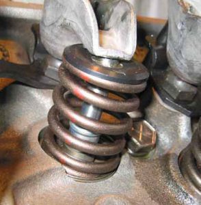
There are several things that can be done to help ensure a successful break-in and prevent premature tappet wear: I prefer to use a moly based cam lube instead of the lighter “red sauce” assembly lubes. If your engine is equipped with a double valve spring as this one is, remove the inner springs for the break-in period, and re-install them once the break-in has been successfully completed. Yes, it means more work for you, but re-installing a set of inner valve springs causes a lot less grief than replacing a flat cam, not to mention it’s considerably less expensive!
If you choose to run a solid lifter cam and “EDM” (“electrical discharge machining”, click HERE for more information) lifters are available, they are a good investment.
The biggest thing you can do to help ensure cam and lifter survival is to use an oil that still has high zinc levels. As it would take several pages of additional information to thoroughly cover this topic, I suggest doing a little reading HERE. Everything you’ve ever wanted to know about oil but were afraid to ask is covered there.
One final thought (for now) on camshafts:
If you intend to run OEM manifolds and a stock exhaust system on your car, you really should give strong consideration to sticking with the OEM cam specs for your engine. The OEM’s spent buckets of money and countless hours developing a camshaft that was optimized for these circumstances, and it’s often nearly impossible to improve on what they provided. An excellent example of this is the GM “143” cam used in the L72, L78 and LS6 engines. When stock iron manifolds are installed, it’s very difficult to beat the performance of this OEM GM camshaft.
Getting back to the subject;
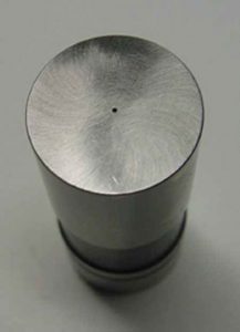
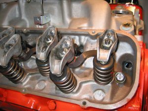
The remainder of the valvetrain consists of solid flat tappet lifters which feature a tiny bleed hole EDM’ed into the contact surface for additional oiling between the cam and lifter (see above pic). Remember that thing about Big Block Chevys having an appetite for flat tappet cams? I’ve used these lifters in previous builds and haven’t lost a cam with them yet, so I’m sticking with them. Pushrods are Comp Cams “Magnum” units which are a 3/8″ 1-piece design featuring .080″ wall thickness and are stock length. Although giant pushrods are making a comeback (and with good reason in modern race engines), the modest cam specs and spring pressures used here don’t require a larger pushrod. Rocker arm studs and pushrod guideplates are genuine GM components. Why? Because they work, and they FIT. If you’ve ever fought to get rockers aligned with the valve tips using aftermarket guideplates, you know what I’m talking about.
Springs are the spec Crane #99893 units for the chosen camshaft, and the locks and retainers are new aftermarket replacements as well. The rocker arms are Crane’s “Nitro Carb” OE replacement stamped steel long-slot units. Why didn’t I use a roller rocker arm? It’s not because I’m cheap, it’s because they simply aren’t needed here. Remember that thing about spending money where it needs to be spent? The ratio is very accurate, and these rockers are more than strong enough to survive this environment.
During initial mock up, the crank and camshaft were installed along with one rod and piston in the #1 cylinder and TDC was verified. Once TDC was verified, the timing set was installed and the cam was degreed in according to the .050″ numbers supplied on the cam card. Some builders prefer to use the ICL method.
Timing chain duty is aptly handled by a standard Cloyes roller timing set. No need for anything exotic here either.
Once the cam was degreed in, a light coat of oil was applied to the piston dome and two small hunks of modeling clay were placed in the valve reliefs. One cylinder head was mocked up with valves and light-weight checking springs, the valves and chamber were also lightly oiled, and bolted down sans the head gasket. Why no head gasket? Two reasons;
1) To verify adequate dome-to-chamber clearance. This is checked once early in the mock-up process before any trial assembly begins, but I prefer to double-verify clearance by making sure the engine turns over freely without interference with the head gasket removed. Once you factor in the thickness of the head gasket, you’ll know you have more than adequate clearance under running conditions.
2) Checking valve-to-piston clearance without a head gasket tightens up the radial clearance around the valve relief. If it clears with no gasket, you know it will have ample clearance with one.
Once the head was snugged down, a pair of lifters, pushrods, guideplates and rocker arms were installed on #1 cylinder and the lash was set to zero. The engine was carefully rotated two complete turns by hand, then the head was removed from the block. The result is two perfect impressions left by the valves in the modeling clay, which give me an accurate way to measure both valve to piston clearance and radial clearance as well. Both valve to piston and radial clearance were more than adequate and neither required any further attention.

While some may consider this method crude, I consider it effective.
The engine then came back apart for the next phase of the build: Checking bearing clearances.
Crankshaft journal diameters were measured and recorded. The main bearing inserts were installed in the block and the caps were torqued to spec, then the bearing diameters were measured. Final bearing clearances were then calculated. This particular crank checked out very well with median figures, and a maximum journal taper of .0002″. (Yes, it’s an Eagle crank, yes it’s standard size, and yes, you read that right. Surprised me too). Journal clearances ranged from .0024″ to .0026″ for the front four mains and .0035″ on the rear thrust bearing.
Speaking of the thrust bearing, this is where I encountered an issue during mock-up. Once the crank was laid in place and the mains were torqued down, there was essentially no measurable thrust clearance no matter where the rear main cap was adjusted to. This isn’t all that uncommon for aftermarket crankshafts, and is easily addressed. The rear main bearings were removed and placed paired-together with their common thrust side down on a machined flat steel plate with a piece of 400 grit sandpaper and gently sanded in a figure-8 motion to remove a small amount of material from the thrust bearing surface. It took two trips to the plate, but the result was a perfectly acceptable .006″ thrust measurement.
The rod bearing shells were installed in the rods, and the caps were torqued to spec using ARP moly lube on the bolt threads as well as under the shoulder of the bolt head to ensure an accurate torque reading.
Snap gauges were again used to measure the rod bearing diamaters, then each rod was assigned to a crank journal based on the previous crank measurements to achieve ideal bearing clearances. Once all critical clearances had been verified, the rotating assembly was sent out to be balanced.
Tech Tip: Clearances should always be verified before balancing in case any machining is required which could change the weight of a component, such as fly-cutting a piston to provide more valve-to-piston clearance.
Once all the parts returned from the balance shop, the rods, pistons, rings and bearings were again matched up for each cylinder according to their previous measurements and assembled to prevent any future mix-up.

Tech Tip: As was the case with this engine, many stroker pistons have the wrist pin located in a position that partially intersects the oil ring groove. This requires some form of additional support to be added to support these sections of the oil ring.
Some pistons utilize a machined aluminum “button” that goes on either side of the wrist pin bore after the pin is installed. These buttons have a ledge machined into them to support the oil ring. Other pistons, such as these, employ an “oil ring support rail” that is installed into the lower side of the oil ring groove after the wrist pins are installed. These rails must be installed before the oil rings are installed. To prevent these rails from turning during engine operation, they have a small indentation that must be placed at the wrist pin bore, facing down.

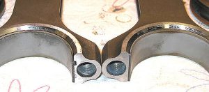
Tech Tip: Aftermarket crankshafts are often ground with a much larger radius in the corners of the journals than an OEM crankshaft to improve strength in this critical area. As such, careful attention must be given to ensure adequate clearance between this larger radius and the edges of the bearing inserts. The bearings used in this build are Clevite “H” series bearings, which are manufactured with a much larger relief on the radius side of the bearing to ensure adequate clearance. Standard “P” series bearings do not have this relief and may cause interference problems with an aftermarket crank that could lead to engine failure if not addressed. Of particular importance here is the fact that the “H” series rod bearings are marked as an upper and lower shell, where the standard “P” series bearings are not. The H series shells MUST be placed in the correct position to ensure adequate radius clearance. Note in the pictures below the shells marked “upper” and “lower”; This pertains to which side of the bearing the additional clearance has been added to. If an upper insert is placed in a cap or a lower insert is placed in the rod, the clearanced side of the insert will face the wrong way.
Note how these rod bearing shells are stamped “upper” and “lower” to indicate their correct positions either in the rod itself or the rod cap, respectively.

Both of these connecting rods were placed with the same (radius) side facing up to illustrate the potential issue. The rod on the left has an Incorrect lower bearing insert installed. The connecting rod on the right has the CORRECT upper insert installed. Note that the radius on the bearing on the left rod is facing the wrong way, and the radius on the bearing on the right is facing the correct side of the rod.
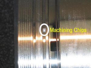
Tech Tip: Pay careful attention during initial parts inspection and cleaning. While we’d all like to believe our favorite parts manufacturers will always provide us with a perfect product every time, things unfortunately just don’t work that way in the real world.
Look closely at the second ring groove in the picture below. The circled object is a rather large chunk of machining debris left over I’m sure from when the ring grooves were machined. It was large enough that it would have certainly prevented the second ring from seating properly in its groove had it been left unnoticed.
At this point in the build, all of the shortblock clearances have been checked, the camshaft has been degreed in, and it’s time to start assembling some parts. Everything, and I mean everything was given another thorough cleaning and laid out for assembly. The main bearings were installed into the block and caps, the rear main seal was installed (making sure it faced the right way), the bearings and the rear main seal were given a light coat of assembly lube and the thoroughly-cleaned crankshaft was carefully lowered into place. The stock main bolts were given a light coat of engine oil and carefully torqued to spec. (no ARP lube here since these are stock bolts, and GM calls for oil on these parts, not moly paste)
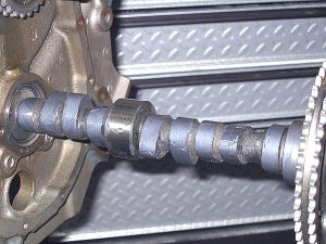
Next to be installed was the camshaft. As you’ll note in the picture below, the cam was given a thorough coating of Crane’s supplied moly lube break-in paste. I do not use the red taco sauce stuff supplied by other cam manufacturers as I’ve found it to have essentially no staying power if subjected to any kind of assembled storage time. Again, this is a matter of personal preference based on what has worked for me over the last 20+ years.
Since everything was pre-checked, checked, then re-checked before any assembly began, the shortblock went together without any drama. The final components to complete the shortblock assembly were the oil pump and pickup tube.
Again, there’s nothing trick here, just a Sealed Power high volume oil pump, a replacement Melling oil pump pickup tube, and a new Melling hardened oil pump driveshaft with an integral collar to replace the crack-prone OEM nylon collar.

The oil pump and driveshaft were installed and torqued to spec, then the oil pump pickup tube was installed into place in the pump body and set to provide 3/8″-7/16″ clearance between the bottom of the screen and the bottom of the oil pan. The shortblock was finally wrapped up with the installation of the timing cover, a stock GM A-body oil pan and the harmonic damper.
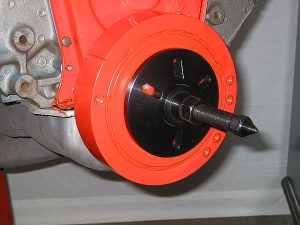
Tech Tip: Please note the use of a proper damper installation tool here. This is the correct way to install a harmonic damper, not by using a hammer. Pounding the damper on with a hammer does absolutely no good to the damper, the crankshaft itself, nor the thrust bearing…even if you use a block of wood. I have seen a damper split in half down the keyway of the snout from being pounded on with a hammer if that tells you anything.
Think about it this way: You’ve just spent how many thousands of dollars on the engine at this point?…and you just can’t seem to justify spending $75.00 on a proper tool to install a damper?
In case you’re wondering why the timing cover and damper are painted but the rest of the engine is not at this point, it’s because these components are impossible to paint properly once they’re installed. As such, they are painted separately before any assembly begins.
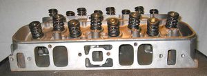
The cylinder heads that will be called into service on this engine are a pair of OEM cast iron rectangle port closed chamber units originally installed on 1970 L78 and LS6 engines. (For those of you concerned with casting numbers, they’re a set of “291” heads)
“Wait a minute! I thought you said this was going to be a budget build. Those heads cost a fortune because all the resto guys want them!”
It’s not just the casting numbers that determine the value of these parts to the resto crowd, but more so the date codes. Original dated parts can cost a fortune, but the dates on this particular pair of heads do not appeal to the resto guys, so I was able to pick the castings up for a decent price. I found this pair at a local machine shop where they’d been sitting gathering dust for quite some time and paid about 1/2 of what the dated castings are going for. These deals are still out there, you just have to look for them.
Now, back to the subject; Yes, I’m running a rectangular port head on the street. There’s another book waiting to be written regarding the debate between oval and rectangular port heads, so for now let’s just say I based my decision on what I’ve built in the past and know works.
The specifics on these particular cylinder heads is as follows:
Intake port volume: 325 c.c. Chamber volume: 107 c.c. Intake Valve dia. 2.19″ Exhaust valve dia. 1.72″
Sharp-eyed readers may notice the 1.72″ exhaust valves instead of the more common 1.88″ size. In a previous life these heads were installed on a Stock Eliminator engine which specified the use of the smaller exhaust valves in the class they were being ran in. There has been no porting on these heads of any kind, nor any polishing, trick milling, chamber modifications, etc. The only “modification” that has been done to them is having the bowls relieved with a throat cutter. However the sharp edges have not been blended in. The heads received a full set of bronze guides (done before I purchased them), new 1-piece stainless steel valves (with stock 3/8″ stems), and a precision 3-angle valve job. It doesn’t get much more basic than this.
For the sake of oil control and to provide increased guide-to-retainer clearance, the top of the guides were machined for the use of PC-style valve seals. I used K-Line seals as I feel they do a superior job of controlling oil over the more popular Teflon seals, especially on a street engine. Again, this is merely a matter of personal preference based on what has worked in the past.
The closed style combustion chambers of these heads offer several advantages over their open-chamber counterparts; two quench surfaces instead of just one, and the smaller chamber size makes it much easier to raise compression levels without having to resort to a big, ugly dome on the piston that adds unnecessary weight and impedes flame travel, and closed chambers provide considerably greater resistance to detonation than open chamber heads given similar compression ratios.

So if these heads are the hot set-up, why did GM go to open chambers?
The main reason was emissions. The closed chamber heads are considered very “dirty” from an emissions standpoint, while open chambers run considerably cleaner. Yes, the open chamber design does tend to flow better due to the chamber walls being moved away from the valves, but it becomes a “trade-off” on an engine like this. In this instance, I’m willing to sacrifice a few cfm of flow in return for two quench areas instead of one and the ability to safely run more compression on pump fuel.
The Crane 99893 valve springs were shimmed to an 1.880″ installed height (+/- .010″) to put seat pressures at spec.

Once again going back to address the potential issue of camshaft failure, the heads were initially assembled using only the outer valve springs. This is to lighten the load on the cam and lifters during the critical “break-in” period. Once break-in was completed, the inner springs were re-installed.
Tech Tip: When assembling big block Chevrolet cylinder heads, I don’t install the guideplates and rocker studs until after the cylinder heads have been installed on the block. Leaving these parts off provides more socket room on the upper row of head bolts and makes torquing the heads down considerably easier.
Tech Tip: Big block Chevrolet rocker studs protrude into the top of the intake port runners. Sealer must be used on the threads or the intake ports will draw oil and air in from the rocker area of the heads causing a vacuum leak and excessive oil consumption. While the exhaust studs “technically” go into blind holes, I still use sealer on them as well just in case any of the exhaust stud holes inadvertently made their way into the water jackets.
As this engine block does not have the three large coolant holes in the deck surface by the lower row of head bolts, Fel_Pro #8180 PT-2 composition style head gaskets were used. Tech Tip: If the block had been equipped with the larger coolant holes on the lower deck surface, a Fel-Pro 8523 PT gasket would have been called for. The 8180 gasket allows full coolant flow at the end of the cylinder head and restricts coolant flow by the lower head bolt bosses, while the 8523 restricts coolant flow at the ends and offers full coolant flow by the lower head bolt bosses.
Most later (1979 and later) MK IV blocks have the larger holes by the lower head bolt bosses while most earlier blocks such as this one do not.

Once both the deck surfaces on the block and on the head(s) were clean, the gaskets were laid in place and the heads were installed. Since OEM Chevrolet big blocks have “wet” head bolt holes (drilled into the coolant passages), sealer was used on the threads on the head bolts. Once the bolts were set in place, a few drops of motor oil were placed on the head bolt bosses of the cylinder heads to ensure the bolts would receive an accurate torque setting.
The heads were torqued to spec in steps of 25, 50 and finally 65 ft.lbs. The lifters were given a coat of moly on their faces and engine oil on the sides, then installed into their bores making sure each one rotated freely. The ends of the pushrods were coated with moly lube, as were the rocker pivot balls and the tips of the valves. The valves were adjusted to .026″ using the “EOIC” method.
The “EOIC” method of adjusting valves:
“EOIC” stands for Exhaust Opening Intake Closing, and is considered the most accurate way to adjust valves. Working on one cylinder at a time, begin by rotating the engine until the exhaust valve for the cylinder you’re adjusting just begins to open. Stop rotating as soon as it begins to open, the adjust the intake valve on that cylinder. Once the intake is adjusted, rotate the engine again until the intake valve on the same cylinder just begins to close, then adjust the exhaust valve. Repeat this process for each cylinder. This method ensures the lifters will be on the base circle of the cam for accurate adjustment.
The factory “163” intake was installed next using new factory reproduction intake manifold bolts. A light coat of thread sealant on the intake bolt threads ensures there will be no oil weeping past the bolts onto the intake.
Firing off the air and fuel mixture will be handled by an OEM points distributor that has been re-curved to provide 14 degrees of initial timing and 36 degrees total timing, all of which is in by 3000 rpm. In lieu of using the original points, a Crane XR-i electronic ignition conversion was installed. While points are certainly reliable, they are also in a constant state of wear as the engine is running. The electronic conversion likely won’t be a source of any additional power, but it should certainly be a source of additional reliability.

As this engine was built to resemble a 49-state 1967 L78 396/375 HP engine, I wanted to stay as close to stock as possible, which meant using an original style GM Holley carburetor. The “correct” carburetor for this particular application is a Holley LIST # 3910 780 cfm vacuum secondary carburetor. (A California car would have received a Holley LIST 3911 carburetor.)
Initial testing was conducted using the “correct” LIST 3910 carburetor, andt for the final testing it was replaced with another factory GM Holley carburetor, this one being a LIST 3418 855 cfm vacuum secondary carburetor, which was originally installed on 1967 L88 powered Corvettes. Remember, this is not a numbers-matching restoration.
On the left is the “correct” 3910 Holley, and on the right is the 1967 L88 Corvette Holley 3418 carb. Take note that both carbs will be fed by a factory 5/16″ fuel line from the brass distribution blocks to the float bowls. Also note that both carbs are equipped with their factory sintered bronze fuel filters. More on that subject later.

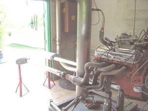
To the dyno!
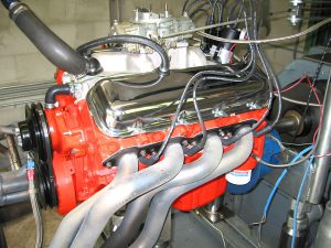
For a dyno facility, I chose the legendary “Ohio George” Montgomery’s shop. George’s shop utilizes an early Heenan-Froud engine dynamometer that is very likely older than I am, but is still considered one of the finest engine dynamometers ever made.
There are a few things to take note of in regards to this particular dynamometer, not the least of which is the fact that this unit is very, very conservative–or in George’s own words, “stingy.” I personally much prefer this over some more modern optimistic dynos. Why? Let me put it like this; how many times have you seen someone buy (or build) an engine that supposedly made outstanding power on a dyno, but can’t back those dyno numbers up on the race track? I’ve seen that happen more times than I can count.
Getting back to the subject;
The engine was loaded on the dyno and filled with 5 quarts of Shell Rotella 15W40 oil for break-in. A set of Hooker 2 1/4″ primary tube early Camaro headers with 3 1/2″ collectors were installed just for the first dyno pull. The 3910 carburetor was bolted down to the intake, and after filling the bowls with fuel, the ignition was turned on and the engine came to life immediately. The ignition timing was set to 36 degrees at 3000 rpm, the coolant was brought up to 180 degrees and the engine was ran under a light load between 2000 and 3000 rpm for 30 minutes to break in the cam and lifters. Once break-in was complete, the engine was shut down and the oil was drained and inspected for any signs of trouble, of which none were found. Once the engine had cooled down, the inner valve springs were re-installed and the lash was again set to .026″.
A total of about ten power pulls were made, of which we recorded six. The dyno pulls were intentionally conducted in a “worst-to-best” manner in order to show how each subsequent change affected the overall power output. Rather than scanning each dyno sheet and posting a picture, the dyno stats will be in text form. In the torque and horsepower columns, the corrected figures will be given, and starting with the 2nd test, in parenthesis next to the torque and horsepower numbers will be a “+” or “-” with a figure representing the change from the previous power pull.
Test #1: 3910 Holley carb jetted 72 primary 76 secondary, 180 degrees coolant temp, timing at 36 degrees, 2 1/4″ Hooker race headers, no collector extensions, flowing into dyno cell mufflers, (“CBT” = corrected brake torque, “CBP” = corrected brake horsepower, “BSFC” = brake specific fuel consumption)
RPM CBT _CBP_ BSFC
3000 522 298 .507
3500 520 343 .491
4000 504 384 .513
4500 479 411 .532
5000 459 438 .541
5500 428 449 .564
6000 414 474 .580
Doesn’t look very encouraging, does it? Note the nasty dip in torque at 4000 rpm. This was caused by the overly-large 2 1/4″ headers. For the next test, the only change was to install a set of Heddman headers (p/n 65002) with 2″ primary tubes and a 3″ collector. No collector extension was used, and again the exhaust flowed into the dyno cell mufflers.
RPM CBT ___CBP _ BSFC
3000 520 (-2) 297 (-1) .511
3500 510 (-10) 340 (-3) .500
4000 526 (+22) 401 (+17) .486
4500 516 (+37) 443 (+32) .493
5000 493 (+34) 470 (+32) .504
5500 438 (+10) 459 (+10) .551
6000 407 (-7) 465 (-9) .590
6500 361 (n/a) 448 (n/a) .661
Note the extremely significant increase in power between 4000 and 5500 rpm! Also note that this time the pull was taken to 6500 rpm, but power was beginning to fall off by then. The slight loss in power from 6000 rpm up is likely due to the fuel mixture being significantly too rich as evidenced by the BSFC #’s hovering at .600+. There is likely some power to be found here by leaning the fuel mixture out at high rpm, but since the 3910 carburetor is only being used for initial testing, no modifications were made to it.
For the next pull, a pair of 3′ long pipes were added to the collectors, and a pair of Walker Dynomax 3″ mufflers (p/n# 17665, which are the ones that will be used on the car) were installed. No other changes were made, other than from this point the power pulls begin at 4000 rpm instead of 3000.
RPM CBT __CBP __BSFC
4000 542 (+16) 414 (+13) .497
4500 519 (+3) 445 (+2) .484
5000 500 (+7) 480 (+10) .488
5500 468 (+30) 491 (+32) .489
6000 427 (+20) 489 (+24) .505
6500 374 (+13) 464 (+16) .565
Yes, you read that right…a 30 ft.lb gain in torque and 32 additional horsepower. Notice how the BSFC numbers calmed down so much with the exhaust in place? That’s the result of proper scavenging, and likely accounts for a good bit of the power increase.
Hard to believe this exhaust added over 30 ft.lbs and 30 horsepower over open headers, but the dyno doesn’t lie.
Next to be tested was the carb swap. No other changes were made, and the 3418 was tuned to factory specifications.
RPM CBT __CBP __ BSFC
4000 526 (-16) 401 (-13) .497
4500 501 (-18) 430 (-15) .546
5000 495 (-5) 472 (-8) .546
5500 457 (-11) 480 (-11) .553
6000 427 (+0) 489 (+0) .619
6500 372 (-2) 461 (-3) .673
Well, that didn’t work too well, did it? Power was down basically everywhere, but wait!…look at those BSFC #’s, they tell a story–this carb is running WAY too rich! Let’s see what happens when we jet the carb down a few sizes all the way around.
RPM CBT ___CBP _ BSFC
4000 534 (+8) 407 (+6) .500
4500 524 (+23) 450 (+20) .491
5000 504 (+9) 480 (+8) .516
5500 454 (-3) 476 (-4) .554
6000 437 (+10) 500 (+11) .571
6500 385 (+13) 477 (+16) .623
Now we’re getting somewhere. The engine FINALLY cracked the 500 horsepower mark, but those BSFC numbers are still indicating a very rich fuel mixture. At this point I need to mention the fact that the 3418 Holley carb was developed for an open plenum intake manifold–that is, one with the center divider milled out of the plenum. Up until now, all testing has been conducted with the plenum divider intact. On the following page, we will remove the intake manifold and have the plenum divider removed, and re-install the intake. For the sake of brevity in testing, the final test will also be with the exhaust heat cross-over blocked, as all testing up to this point has been done with the cross-over open.
The intake manifold was removed and the center divider in the plenum was removed for the next test. It is necessary to mention here that while popular opinion has it that removing the divider hurts overall power and driveability, few people seem to take into account that the carburetor needs to be set up to work in conjunction with an open plenum manifold. Chevrolet addressed this with three different carburetors, all of which were intended for open plenum intakes; the 3418 carburetor was used on the 1967 L88 Corvette, the 4054 Holley was used on the 1968 L88 Corvette, and the 1969 L88 Corvette (along with the fabled ZL-1 Camaro) utilized a 4296 carburetor, which was the only mechanical secondary carb used on these production big block engines. All three carburetors are rated at 855 cfm, but the 3418 and 4054 are vacuum secondary units.

So let’s see if going to all the trouble to remove the manifold, mill the plenum divider and block off the heat cross-over passage was worth it.
RPM CBT _ _CBP_ _ BSFC
4000 546 (+12) 417 (+10) .483
4500 544 (+20) 467 (+17) .454
5000 531 (+27) 505 (+25) .493
5500 488 (+34) 512 (+36) .507
6000 467 (+30) 534 (+34) .536
6500 417 (+32) 517 (+40) .580
Now that’s more like it. Amazing what can happen when the carb and the intake start to work together, isn’t it? Both torque and horsepower were up significantly across the board, and with a peak of 546 ft.lbs at 4000 rpm, I’d say that puts to rest the myths that rectangle port heads and open plenum manifolds can’t make torque. Remember…the only non-stock items in this engine that can legitimately be considered “power producers” are the 1/4″ additional stroke and the relatively moderate solid lifter cam. There is still plenty of power left in this combination however–remember that the cylinder heads have absolutely no port work done to them and are only equipped with the small 1.72″ exhaust valves. The BSFC is still indicating a rich fuel mixture at high rpm, although nowhere near as bad as it was with the plenum divider intact.
Let’s recap the power curve and compare the initial power numbers with the final pull;
RPM CBT ___CBP _ BSFC
4000 546 (+42) 417 (+33) .483
4500 544 (+65) 467 (+50) .454
5000 531 (+72) 505 (+67) .493
5500 488 (+60) 512 (+63) .507
6000 467 (+53) 534 (+60) .536
6500 417 (n/a) 517 (n/a) .580
In six pulls on the dyno, the engine picked up 72 ft.lbs of torque and nearly 70 horsepower just by making things work in conjunction with each other. If this doesn’t stress the importance of the overall combination, then I don’t know what does.
Important information please read:
As was mentioned previously, this engine utilized a stock oil pan, and Shell Rotella 15W40 diesel motor oil was used. During dyno testing, the engine exhibited some unmistakable signs of windage and/or oil foaming issues. As the engine surpassed approximately 5500 rpm on the first three pulls, a moderate amount of smoke began to emit from the exhaust, and as the throttle was closed, a significant amount of smoke came from the exhaust. On a hunch, I disconnected the PCV tube from the base of the carburetor before the next pull. Doing so completely eliminated the oil smoke from the exhaust. There contributed to the issue; the OEM oil pan is beyond its design parameters in trying to provide oil control with a larger-than-stock rotating assembly, and secondly, the Rotella oil is not designed for high RPM use, and as such did not have much in the way of anti-foaming additives. There was also a slight drop in oil pressure on every pull between 6000 and 6500 rpm–not enough to cause alarm, but enough to indicate there are definite oil control issues present. Please take this into consideration should you decide to build something similar. I will be installing a higher-capacity oil pan on this engine before it goes in the car.
In closing, I want to re-emphasize the point of this build lest it get lost amidst the sea of magazine tripe people have unfortunately been fed for far too long; The goal here was to prove that you do not need all the latest aftermarket parts to build a streetable engine that can still crank out great numbers. This build proves that factory parts are easily capable of generating some rather stout power figures, and best of all, they tend to cost considerably less than their aftermarket counterparts. I fully expected this engine to surpass 575 horsepower and 575 ft.lbs of torque before its all said and done, and again, this is without using any “trick” parts.
One final note to add; during all testing on both carbs, the fuel lines feeding the float bowls were the stock 5/16″ size, and both carbs were equipped with their OEM sintered bronze fuel filters. I guess this dispels the myth that you need a giant fuel system to make these kind of power figures, doesn’t it? There is a lesson to be learned here; clean fuel is essential for proper carburetor function, and as evidenced here, the OEM sintered filters obviously do not pose a fuel restriction. Leave the filters IN your carburetor! Should they happen to become clogged with debris, they are equipped with a bypass spring to allow fuel to flow past the clogged filter until it can be replaced. As a part of routine maintenance, just replace your fuel filters once a year and your carburetor will thank you for it.
That wraps up the original phase of this build. After some time in the car, the engine began to smoke more & more out the exhaust. The problem was traced down to poor ring seal due to faulty machine work during the original phase of the build, so in 2014 I pulled the engine back out to address the issue. Be sure to read the second part of this project, the results surprised everyone involved–even ME!