1969 Z28 302 Crossram Project:Taming a Wild Mouse
In the late 1960’s and early 1970’s, horsepower ruled the streets. Every auto maker from AMC to Pontiac had a variety of performance options available for those whom spirited driving was a priority.
Chevrolet was certainly in the game as well, turning loose on the streets one of the wildest animals ever to roam the roads–the 1969 Z28 Camaro with its high-winding 302 cubic inch small block screamer. Despite its diminutive displacement, the little 302 “mouse motor” quickly became a force to be reckoned with on the street and the strip.
The 302’s main advantage on the street was actually its lack of low-end torque, and its ability to make strong power at an rpm level where most other engines were starting to sign off. While the torque-laden big block powered rides were often fighting for traction, the high-winding little 302 could quickly put a considerable gap between itself and its competition, and by the time 4th gear came around it was all over but the crying.
Given the fact that the 302 was developed mainly for the race track, one would expect such an engine to be a high-rpm screamer. For those who considered “too much” to be “just right”, GM also offered an over-the-counter optional crossram intake manifold with a pair of 585 cfm Holley carburetors to replace the factory dual plane high-rise manifold and 780 cfm Holley carburetor. Putting aside the potential for increased power output, the crossram had one other thing going for it as well–a rather stunning visual impact. Even today, 40 years after its introduction, when the hood comes up on a crossram-equipped car, a crowd is quick to gather. An obvious perk for the street crowd.
In practical application, the crossram intake system added notable power in the upper rpm ranges, which was exactly what was needed on the race track. However, with its huge common plenum design, the crossram intake made the 302’s already-lacking low-end torque situation even worse. Not a problem on the track where the engines seldom saw the low side of 5000 rpm, but definitely not ideal for street use.
Even in stock form, the 302’s lack of low-end torque often made for somewhat labored street manners under less spirited driving conditions. A wide-ratio 4-speed transmission was a welcome addition behind many 302’s, as were rear end gears well into the 4-series range and beyond. Excellent for racing, not-so-hot for daily commuting. Road trips? Only for the bravest of the brave. In the simplest of terms, a 302 needed to rev to do its thing.
Even so, this didn’t deter people from running a crossram intake system on the street in the never-ending quest for more power. The results were what one should expect…even less low-end power, making daily driving even more laborious.
Despite these issues, there are still many die-hard enthusiasts who are willing to take on the challenge of running a crossram system on the street. One such enthusiast is Indiana resident Gary Westveer.
In November 2006, Gary contacted me about building a 302 crossram engine for his rotisserie-restored 1969 Z28 Camaro project. Gary wanted a strong running engine that remained true to its racing heritage, but it also needed to be docile enough to take on a small road trip should the desire arise. Not an easy task given the circumstances, but after discussing several options with Gary, I agreed to take on the project.
My job was clear;
I had to tame the wild mouse.
Follow along with the build-up and see the final results as my work is put to the test on the dyno.
The project started off with a correct 302 warranty replacement “CE” block, complete with 4-bolt mains and factory windage tray studs. The shortblock was complete when purchased, but upon disassembly and preliminary inspection, the connecting rods were deemed unserviceable, and although the bores were still standard, they were just outside of acceptable limits for a street-bound engine. Before any machine work began, the block was pressure checked and inspected for cracks to ensure there wouldn’t be any nasty surprises once the engine was up and running. Everything passed with flying colors.
The block was treated to a .030″ overbore and honed for a street moly ring set. The deck surfaces were left un-touched to spare the engine codes. The main bearing bores were checked for alignment and size and were found to be acceptable. Once everything had been inspected, machined and cleaned, all that was left to do was install a fresh set of cam bearings and oil galley plugs.

One freshly machined and cleaned small block Chevy ready to be built
The crankshaft is an original GM “1178” forged steel unit which was in the shortblock when it was purchased. The crankshaft was magnafluxed and checked for straightness and found to be 100{e8a31ad70eb76b9d1736af28c4c10c5ce60babf18dd7728d2fa05ac44ba5f2cd}. Both the main and the rod journals had already been turned down .010″-.010″ during a previous life, and needed no further attention other than the obligatory polish job.

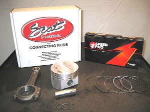
No trick parts required here!
To fill the voids left where the original pistons and rods once resided, a set of SRP forged pistons were called into service, along with a set of Scat 5.700″ I-beam connecting rods fitted with ARP rod bolts. A Speed Pro moly ring set was chosen to handle the duty of sealing up the cylinders.
As is standard practice during the initial mock-up phase of a build, the main journal sizes were measured and recorded. Next, the main bearing inserts were installed in the block and the main caps were torqued to spec; the bearing diameters were recorded and bearing clearances were calculated. The same process was repeated for the connecting rod journals and connecting rods as well.

Next up on the checklist was to measure the crankshaft thrust clearance. The crankshaft was lowered into the main bearings, the rear main cap was aligned, and the caps were installed and torqued to spec. The thrust measured out at a perfect .006″. As a side-note; the thrust clearances are checked at several points of crankshaft rotation just to make sure there is no binding or tight spots.
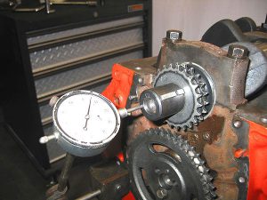
Next on the “to do” list was to temporarily install the #1 piston & rod and verify true TDC. Once this was verified, the camshaft was degreed in. (More on the camshaft on the next page)
Keeping the crankshaft and the camshaft harmoniously connected was left to a Cloyes double roller timing set.

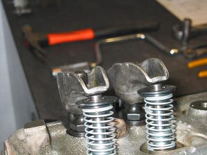
One of the last things to do during preliminary mock-up is to check the valve-to-piston clearances. A set of lightweight “checking springs” were installed on the cylinder head for the #1 cylinder location. Next, the chamber, the valve faces, and the piston dome were given a light coat of oil and two small portions of modeling clay were pressed into place in the radii of the valve reliefs.
The cylinder head was placed directly on the block (sans head gasket) and two cylinder head bolts were snugged down to keep everything in place. Next, a pair of lifters, pushrods and rocker arms were installed and the valve lash was set to zero. The crankshaft was then carefully rotated two full turns to run the valve train through a complete cycle. The valvetrain components were removed followed by the cylinder head. The compressed clay sections were carefully measured to check for both horizontal and radial valve clearance. Given the generous valve reliefs of the SRP pistons and the (relatively) modest camshaft timing, ample valve-to-piston clearance was present.
Once the final mock-up was complete and all clearances were verified, the rotating assembly was sent out for balancing. Prior to the final assembly, everything was cleaned within an inch of its life.
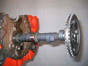
The first component to go into the block was the camshaft. While we’re discussing the camshaft, I should mention that I deliberated long and hard before finally deciding on a cam to use for this engine build . Given the rather modest displacement of the engine and the rather generous plenum volume of the intended crossram manifold, I was very concerned with trying to build a respectable amount of low-end torque without sacrificing higher-rpm power.
The factory camshaft for the `69 302 Z28 engine specs out with 254 degrees of duration at .050″ on both the intake and the exhaust side with .485″ gross lift (.455″ net with lash) with a 114 degree LSA and an intake centerline of 112 degrees. If I may be so bold as to state, I consider the 302 Chevrolet engine grossly over-cammed from the factory for a “production passenger car” engine (albeit a thinly disguised race engine at heart), and is one of the main reasons even a stock 302 lacks low-end torque.
Consider this: The 1970 350 cubic inch LT1 engine which replaced the `69 model year 302 was essentially identical to its predecessor save for two things; .480″ additional stroke, and a smaller camshaft!
Taking this cue from the General, I chose an off-the-shelf solid lifter camshaft with 10 degrees less intake duration and 2 degrees less exhaust duration than the factory `69 cam.
The camshaft part number and specifications will not be divulged, but I will say that aside from the previously mentioned differences in duration compared to the OEM camshaft, the cam I selected has slightly more lift on both the intake and exhaust side, and there is a significant difference in lobe separation angles and lobe centerlines as well. Again, this was all carefully chosen in an effort to maximize driveability and lower rpm torque without sacrificing excessive upper rpm horsepower.
(Note: The cam I selected mandates the use of tubular exhaust headers. It would not work well at all with OEM iron exhaust manifolds)
There is much more that could be discussed here regarding camshafts, but for the sake of brevity I’ll conclude this part by stating that this cam worked out even better than I had anticipated. But you’ll just have to finish reading the article to see the final dyno numbers.
No red Taco sauce here, only tried and true Moly paste!
Once the cam was installed, the rest of the shortblock was assembled. Since everything was checked several times during mock-up, the short block went together without any drama.
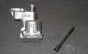
The last components to go into the lower end of the engine were a Melling M55HV oil pump (the older casting with the thicker neck, not one of the newer lightweight castings!) and a new Melling one-piece hardened oil pump driveshaft. I consider these one-piece shafts a must-have for any kind of a performance build-up. The stock nylon collar is fine for grandma Mirdle’s 305 Caprice wagon engine, but it has no place in an engine like this.
Lastly, a new OE replacement oil pickup screen was installed into the pump before the timing cover and the oil pan (again, a correct `69 vintage Z28 unit complete with internal baffling) was bolted into place.

With the short block wrapped up, it’s time to turn our attention to the cylinder heads.
The cylinder heads used on this engine were a pair of 1969 vintage “186” castings, which are the correct castings for a 302 engine. However, this particular pair of castings actually started out as a more pedestrian set of passenger car heads which were originally equipped with 1.94″-1.50″ valves. While some purists may scoff at the thought, given the scarcity of original 2.02-1.60 valve heads that haven’t been hammered to death, starting with a pair of 1.94 valved heads is actually a preferable alternative. Using these castings allows the user to open the seats up to accept the larger valves, thereby starting with virgin metal to cut valve seats into. Original 2.02 heads with sunken valve seats are nearly impossible to repair since there’s very little room to cut them for hardened valve seats without cutting into a water jacket, thereby ruining the head.
Again, before any machine work was performed, the castings were magnafluxed to ensure we weren’t going to end up with an expensive pair of bookends. Next, the deck surfaces were checked for straightness, and again, everything passed with flying colors.
The heads received a full set of bronze guides, and the tops of the valve guides were trimmed for additional retainer-to-guide clearance and to allow the use of “PC-style” valve seals. Instead of the more traditional teflon seals, a set of K-Line seals were installed as I personally feel they do better job of oil control in the long run.
Once the heads were machined for the larger valves, a plunge cutter was used to open up the valve bowls to help blend in the ridges left by opening up the seats. The seats were then given a 3-angle valve job. (No porting of any sort was done to the heads)
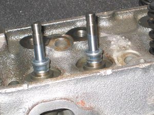
The final machining step was to remove the factory pressed in rocker studs and convert the heads to use screw-in studs and pushrod guideplates. It is worth noting here that despite what many believe, original `69 302 Z28 heads did not have screw-in studs and pushrod guideplates from the factory. However, this is considered a worthwhile conversion, even if it’s not 100{e8a31ad70eb76b9d1736af28c4c10c5ce60babf18dd7728d2fa05ac44ba5f2cd} “factory correct”.
Once the heads were machined, a new set of stainless steel one-piece 2.02″-1.60″ valves were installed, the valve spring installed heights were set, and the heads were assembled.
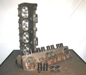
Nothing trick here, just good quality factory performance cylinder heads and quality machine work.
K-Line valve seals were used instead of the more traditional teflon components as I feel they do a better job of oil control in the long run…a must for a street engine!
With the heads assembled and ready to install, it was time to prep the head gaskets. Here’s where I took a somewhat unusual approach in an attempt to keep some compression in the engine.
Given the fact that the block was correctly coded as a 302 warranty block, the deck surfaces could not be cut to true them up and to bring the pistons up closer to the deck height. During mock-up, the pistons were measured to be ~.023″ down in the hole. If you were to combine that with a common .039″ (or thicker) composition head gasket, you would be left with an excessive quench distance of .060″+ which not only “wastes” compression, but makes the engine more prone to detonation or “spark rattle”.
As such, I decided on a pair of Fel-Pro .015″ thick steel shim head gaskets, much like the style used on these engines originally back in the day. Combining the .023″ deck height with a .015″ gasket results in a much more favorable .038″ deck clearance figure. Given the technology of gaskets today, this style of gasket has somewhat fallen out of favor, but as evidenced here, there is still a time and a place where they are more than adequate and work quite well with the appropriate pre-installation preparations. In this case, it was simply a matter of cleaning the gaskets and giving them several light coats of Permatex Copper Coat spray, allowing each subsequent coat to tack up slightly before applying the next.
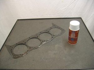
This may seem somewhat “old school” to some, but it works!
Once the gaskets had a little time to tack up, they were placed on the block and the heads were carefully lowered into place. A set of OEM head bolts were cleaned, and a daub of thread sealer was applied to the threads before the heads were torqued down in 3 steps of 25 ft.lbs, then 45 ft.lbs, and finally 65 ft.lbs.
Once the heads were in place, the rest of the valve train hardware was installed. Given the widespread epidemic of flat-tappet camshaft failures in recent years, I’ve been using “EDM” lifters whenever they are available for whatever I am working on. These lifters start out as a conventional solid tappet, but are modified with a tiny “bleed hole” machined into the face to provide constant additional oiling between the camshaft lobes and the face of the lifters.
To learn more about EDM machining, click HERE.
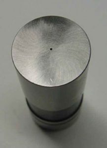
The tiny bleed hole provides a constant supply of oil to the cam lobe surfaces
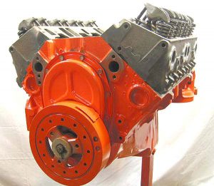
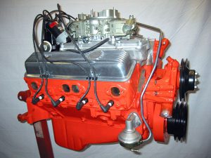
It’s starting to look like an engine again.
Here’s where things start to get interesting.
Forget about tunnel rams. Forget 6/71 blowers.
You really wanna draw a crowd at your favorite local choke & puke burger joint?
Bolt one of these bad boys down on your engine and you’ll draw a crowd before you know it.
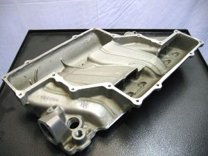
The GM crossram intake manifold is one of those speed components from yesteryear that’s developed an almost cult-like following. There is absolutely no denying the visual impact one of these induction systems presents.
However, for all their eye-appeal, they’re not without their drawbacks. Aside from what was discussed at the beginning of this write-up, something else to consider is the fact that these systems are insanely expensive, even if you decide to use a reproduction intake manifold and service replacement carburetors. If you simply must have original dated stuff, be prepared to spend more than most people probably spent on the downpayment on their house.
Secondly, as I’ve mentioned repeatedly now, one must realize that this system was never intended for street use, it was developed purely as a race system. As such, the carburetors have no provisions for chokes (making warm-up a bit challenging), and again, the giant common plenum design of the intake puts a serious dent in low rpm power.
Lastly, these intakes aren’t exactly a “bolt-on” deal. Among other things, you’ll have to modify an elbow adapter to clear the oil pressure sending unit on the back of the block. If you intend on running a set of factory aluminum valve covers, be prepared to make some significant modifications to them (more on that in a moment).
However, if you’re willing to make these sacrifices, then a crossram system may just be what you’re looking for.
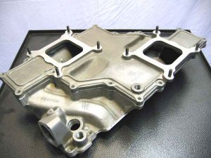
The fun is just beginning!
Below, with the plenum lid removed, you can see the long, straight runners and the giant common plenum that makes this manifold work.
Now that we’ve figured out how we’re going to get the air and fuel mixture into the engine, we need to light it off.
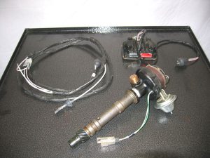
This engine employs a somewhat unusual ignition system–again, one that was quite popular “back in the day.” originally developed for NASCAR racing, this is GM’s transistorized ignition system.
This particular distributor has been re-curved, again in an attempt to maintain as much low-end power as possible. This distributor is set to provide 14-16 degrees of initial timing, and 36-38 degrees of total timing, all of which is in by 3000 rpm.
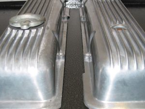
Adorning the flanks of the crossram intake is a pair of original cast aluminum Z28 valve covers.
This particular pair still retain their original cast-in drippers, which help direct oil to the rocker arm fulcrums.
If you’re running aftermarket rocker arms, these drippers may interfere with them.

With the top of the engine rapidly coming together, I went to install the valve covers only to be greeted by this!
Here’s another crossram “quirk”; the plenum flange is too close to the rocker arms to allow the valve covers to pass between them.
If only that relief cut into the valve covers was a little deeper and a little longer…..

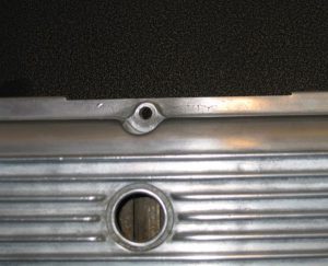
Below, you can see the factory relief notch cut in the top of the valve cover.
This was done to clear the top of the intake runners on the `67-on-up factory aluminum highrise intake manifolds. Unfortunately, this relief is neither deep enough nor does it extend far enough down the length of the valve cover to allow valve cover installation with the crossram intake.
So what’s the solution?
Finish the job the factory started.
Yes, it’s a rather unpleasant feeling carving up a set of original 1969 Z28 valve covers, but this is one of the sacrifices one must make in order to run them with the crossram intake.
The factory reliefs were cut the rest of the length of the valve cover, and they were also cut deeper by approximately .080″.
With this modification, the valve covers slipped into place with only minimal fussing.
The valve cover gaskets were trimmed to match the relief.
With the valve cover debacle now resolved, all that was left to do was install the rest of the engine peripherals and get it ready to go to the dyno.
The mechanical fuel pump and fuel feed line to the distribution block were installed to make sure everything fit correctly, then were removed since they are not needed on the dyno.
The thermostat was also left out temporarily as the engine dyno will regulate the engine temperature, and a thermostat would only interfere with dyno function.
The carburetors are a pair of original dated 4295 crossram units restored here in-house at Vintage Musclecar Parts.
For a dyno facility, I had to look no further than the legendary “Ohio George” Montgomery’s Speed Shop.
If you don’t know who “Ohio George” is, then you’re either too freshly out of diapers or you’ve been living under a rock.
Rather than me typing out numerous pages in a vain attempt to even remotely cover some of George’s accomplishments, please take a look at his website and see for yourself:
George and his son Gregg are pictured below:

Before I go into detail about the dyno results, please remember that this engine was not intended to be a race engine, and as such, we were not on a quest to find every last ounce of power the engine had available. I had a target power figure in mind I hoped to hit, and that power level was achieved on the very first pull. The only “tuning” that was done was to set the timing to 36 degrees.
The engine was loaded in place on the dyno, and the accompanying life support systems were installed. Rather than use a set of large tube dyno headers, we used the actual headers that will be installed in the car with this engine–a set of Hedman 1 5/8″ primary tube street headers with 3″ collectors.
The fuel pump was turned on to fill the carbs with fuel, and after a couple of “tweaks” to get the reproduction fuel lines to dry up, we were ready to make some noise.
The engine came to life and was brought up to a fast idle to break in the camshaft & lifters, and the ignition timing was set to 36 degrees total. The engine coolant temperature was set at a steady 200 degrees to help everything seat in.
After 30+ minutes of running time, the engine was shut down and following a quick spark plug check, was allowed to cool overnight.
The following day, the oil was drained and inspected for any signs of break-in trouble, of which absolutely none were found.
5 fresh quarts of Shell Rotella 15W40 oil and a new Purolator oil filter were installed and the engine was once again brought to life. Once the engine was warmed up to temperature, one relatively easy power pull was made from 3000 rpm to 6000 rpm, taking readings at every 500 rpm intervals.
Again, remember, this is NOT a race engine, and these numbers are not some bogus inflated “west coast magazine” dyno numbers. These are real-world numbers achieved on a very conservative dyno.
The numbers?
377 horsepower at 6000 rpm and 355 ft.lbs torque at 4500 rpm. (If you want the “west coast” numbers, tack on 15{e8a31ad70eb76b9d1736af28c4c10c5ce60babf18dd7728d2fa05ac44ba5f2cd}-20{e8a31ad70eb76b9d1736af28c4c10c5ce60babf18dd7728d2fa05ac44ba5f2cd}.) My target power number was 375 horsepower. We made another pull just to make sure we weren’t leaving anything on the table. The second pull was to 6500 rpm, and the engine was on the downside of its power curve by then.
Consider the factory (admittedly conservatively) rated the 302 engine at 290 horsepower at 5800 rpm and 290 ft.lbs. torque at 4200 rpm.
I was pleased with the torque output, especially taking into consideration the crossram manifold. All in all, I am very happy with the way this engine turned out.
I’m sure had we wanted to, we could have spent the rest of the day experimenting with timing and valve lash and we could’ve probably snuck up on 400 horsepower, but that wasn’t what this engine build was all about.
The original goal was to take a 302 cubic inch engine, equip it with a crossram intake manifold system, and make it driveable while still retaining strong upper rpm power figures.
I’d say those goals were met.
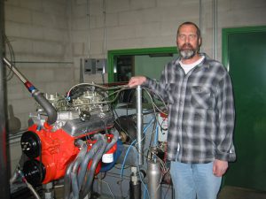
The owner, Gary Westveer, standing next to his rather stout little 302 crossram engine just after the final dyno pull was made.
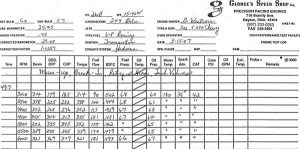
Below is the actual dyno sheet for the engine. Please note the “CHP” (“corrected horse power”) and torque columns. Notice that from 3000 rpm to 6000 rpm that the torque never fell below 300 ft.lbs, and peaked at a realistic 4500 rpm. This should provide for a very driveable engine on the street, which again was the primary goal.